Categories
- PID Controllers
- Auto gauges, EGT Boost
- Coffee Machine Kits
- Brew Equipment
- Power Regulators
- Powder Coating Equipment
- Powder Coating Ovens
- Smoker Controllers
- Humidity Controllers
- Plug-n-Play Controllers
- Thermometer, Process Meter
- Temperature Sensors
- SSRs & Contactors
- Timer, Counter, Tachometer
- Pressure Controller
- Controller for Coil Heater Enail
- Enclosures (Boxes)
- Switches
- Punch & Die for Control Panel
- DIN Rail Components
- Connectors
- Accessories
- Control Panels & DIY Kits
- Sous Vide Cooking
- Liquid Dispensing Machine
- Controller For Lab Research
- Silicone Tubing (Platinum Cured)
- Value Packs
- Scratch/Dent/Refurbished
- Services
- Specials ...
- Featured Products ...
- All Products ...


Featured [more]

Wi-Fi 1/16 DIN PID Temperature Controller with Ramp/Soak
Save: $10.00 off
Temperature Sensors
1. What can I use to extend my RTD wire?
You should use regular copper wire for the RTD sensor connection. The only requirement is that the wire should not be thinner than 26
2. What can I use to extend my thermocouple wire?
You must maintain the same dissimilar metals to the instrument. You need thermocouple wire or thermocouple extension wire to extend the thermocouple wire. The B type thermocouple is the only type that can be extended with copper wire.
3. How to join the thermocouple extension wire?
You can use a regular copper wire splicer to crimp them together. As long as the splicer is short, it is fine.
4. The measurement on the controller is not consistent with other standard, is my controller or thermocouple (TC) defective?
It is not necessarily defective in that case.
1) Expected Accuracy
All temperature controllers that Auber sells have an accuracy of 0.2% of the range. For a K type thermocouple, that translates to +/-5 °F. Most of time, the error is within 2-3 °F. If the error you get is more than 5 °F, something is wrong.
2) Statistics of Auber Equipments
-
The probability of having a defective controller that could not read the K thermocouple within specification is less than 1%.
-
The probability of having a defective K thermocouple is less than 0.1%. For more than tens of thousands of thermocouple we have sold, we had less than 5 that could not read correctly.
-
For the customer that has problem of inaccuracy, the probability that customer didn’t set the controller correctly is about 1-2%.
-
For the customer that has problem of inaccuracy, the probability that customer didn’t use the thermocouple correctly is >95%.
So, you should have good confidence that the Auber equipment is most likely not the cause of the problem.
3) Isolating the Problem
a. The first thing to do is to verify that the controller is OK. This can be done very easily. Just use a copper wire to short the terminals for the TC input (e.g connect terminal 4 and 5 for 2342 or 2352; connect terminal 6 and 7 for 1512, and connect terminal 9 and 10 for 2363). The reading of the controller should be around the ambient temperature, where the controller is located.
If that is the case, the controller is fine. To be 100% sure the controller is fine; check the parameter setting for the input type. Make sure it is set to K type.
If reading does not show ambient temperature, change all the parameters to the default settings listed in the instruction manual. If it still does not display ambient temperature, the controller is defective.
If “a” passes, go to next step.
b. The next thing to do is to verify that the system (the controller and the sensor) is OK. You need to remove the TC from your installation, connect it directly to the controller (without extension and connectors). Dip the TC in ice/water mixture (70 : 30 ratio). The sensor body needs to be completely immersed. Read the temperature after 5-10 minutes. The reading should be close to 0°C or 32°F. You can also do this in boiling water. The reading should be close to 100°C or 212°F at sea level. Important: you cannot calibrate the system in the air because some of the sensors may take 30 minutes for response in the air.
If the system fails to pass “b”, then the TC may be defective.
If the system passed test “a” and “b”, then the problem is the set up. Here is a list of the most common problems reported:
a. Wrong type of sensor style is used.
For air measurement, the most common problem is that the wrong style sensor is used. To measure the temperature of the air, the thermal mass of the sensor has to be small. For example, the TC-K3 probe is designed to measure metal temperature such as plastic injection mold. In the air, the response time is about 15 to 20 minutes. It is not suitable for control the temperature of air. For air measurement, the sensor should be thin with low thermal mass. Normally, for an oven, the sensor should not be more than 5/32” (or 4 mm) in diameter. A 1/8” (or 3 mm) diameter probe is preferred. For very fast response, you will need to use the “bare” wire thermocouple.
For liquid and air measurement in a container, the length of the probe is also important factor if the sensor is mounted on the wall of the container. Normally, the temperature by the wall is lower than in the center. If the sensor is very short, the mounting on wall will function as a heat sink, it will drain more heat than the probe tip can pick up, making the reading constantly lower. Normally, the probe should be at least 4 in (100mm) from the wall. If possible, an insulated mounting, such as a plastic mount instead of a metal mount, will help.
b. Wrong extension wire is used.
If the TC is not directly connected to the controller, the extension between the controller and TC is a common problem.
a) The most common problem is that the wrong polarity used. The main reason is that there are too many color codes for the K type thermocouple. Most people think the red wire is positive. For the
This is problem is very difficult to figure out unless you are experienced with TC. Many brewing plants need long TC cable for the extension. We have had several customers that had a hard time to figure out the problem.
b) The second common problem is the wrong type of wire. The extension wire used has to be same K type TC wire or K type TC extension wire. You can’t use regular copper wire.
c. Ground loop and interference.
TC signal is a mill volt level high impedance signal. It is very susceptible to the RF and ground loop interference. The heating element, pump and fan can all produce significant interference to the controller reading. If the reading is accurate until you turn on the heater or pump, you know that there is a ground problem. The grounding of a system is a very tricky issue; each system might have different problems. Here is a list of some common problems:
a) Ground loop. You should put all the ground wire to a single point, not all over the cabinet.
b) Unshielded TC. The circuit ground of the controller is normally floating. If the TC is unshielded (or not well shielded) and tip is touching a large electrolyte object, the TC can become an antenna that picks up all kind of noise. Normally, the negative input of the TC on the controller circuit board is the circuit ground. You can connect the negative input terminal to a sable metal chassis to function as a stable electric field reference.
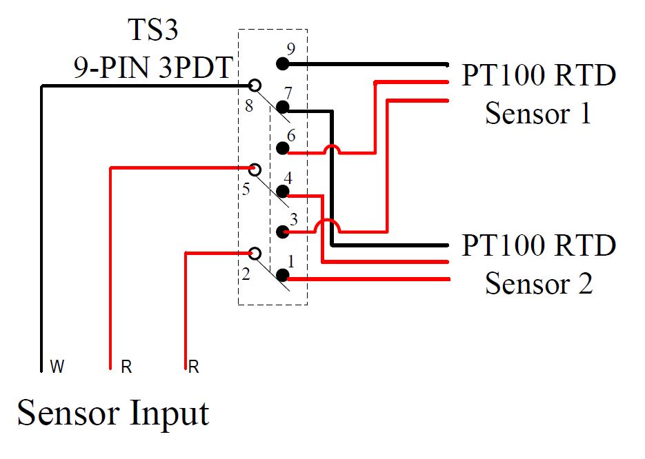
5. How to use a switch to select sensor input.
Wiring Example 1. Selecting from two PT100 RTD sensors by a toggle switch – switching all three wires.
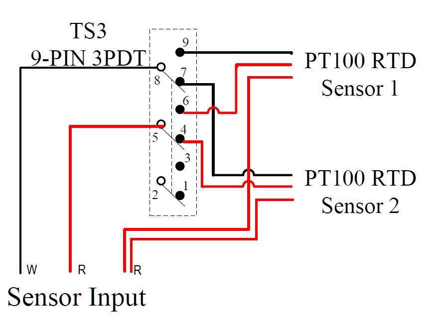
Wiring Example 2. Selecting from two PT100 RTD sensors by a toggle switch – switching two wires.
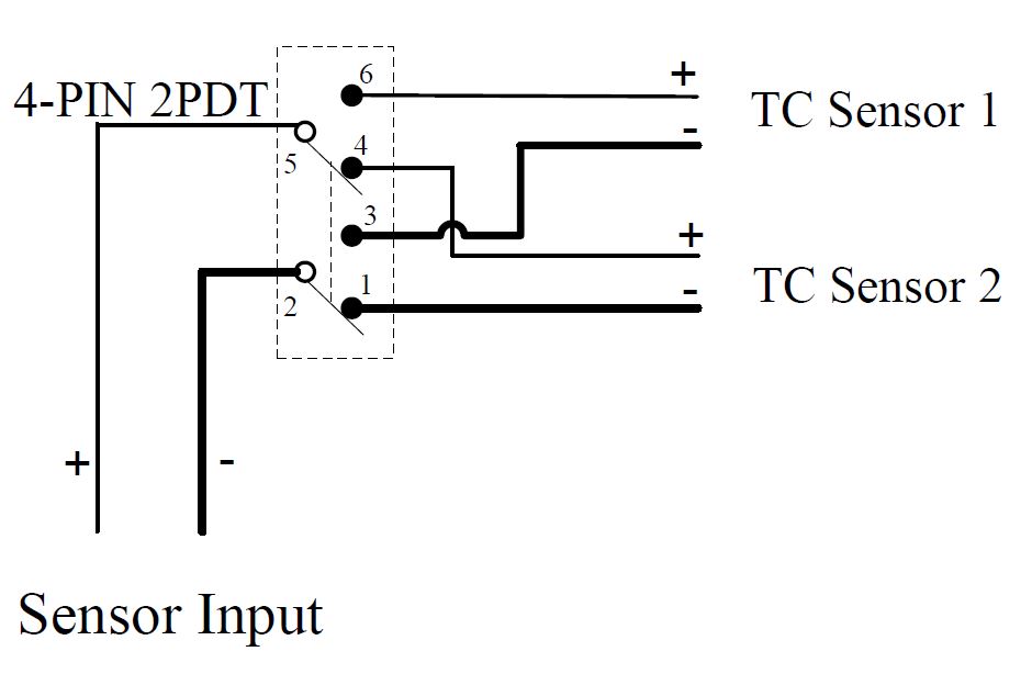
Wiring Example 3. Selecting from two thermocouple sensors by a toggle switch.
6. I think my temperature sensor reading is inaccurate. How I can prove it?
(short link: https://bit.ly/sensorcal )
If you are concerned about the reading accuracy, you can test your temperature sensor in ice water mixture and boiling water. You can also make an ice bath to do a one-point calibration. The ice/water mixture should contain 30% of water and 70% of ice. Please make sure your sensor is fully immersed. We have this guide regarding verifying the reading in ice bath. And this video link may also help. You can also do a similar testing in boiling water. If the reading is accurate on both points, the reading should be accurate for all the range. If you have another thermometer, you can calibrate them at the same time.
If you have couples of degree reading difference on the display, you can use the offset parameter in your controller/meter to offset it.
7. What is the difference between the type k thermocouple and PT100 RTD temperature sensor?
Both type K thermocouple and PT100 RTD sensors are popular temperature sensors on the market. Generally speaking, type k thermocouple can reach a very high temperature (up to 2300F, vary by the probe material and design) and PT100 RTD sensor can only reach up to 500F (some high RTD sensors can reach 800F, such PH7090). In addition, type K thermocouple is economical but less accurate (typical ±5F before the calibration). PT100 RTD has higher accuracy (within 1F). Thermocouple has slightly faster response time than RTD.
For application, type K thermocouple is recommended for high temperature applications such as powder coating oven, smoker, etc. PT100 RTD sensor is recommended for high precision, medium to low temperatures applications, such as home brew, distilling, etc.
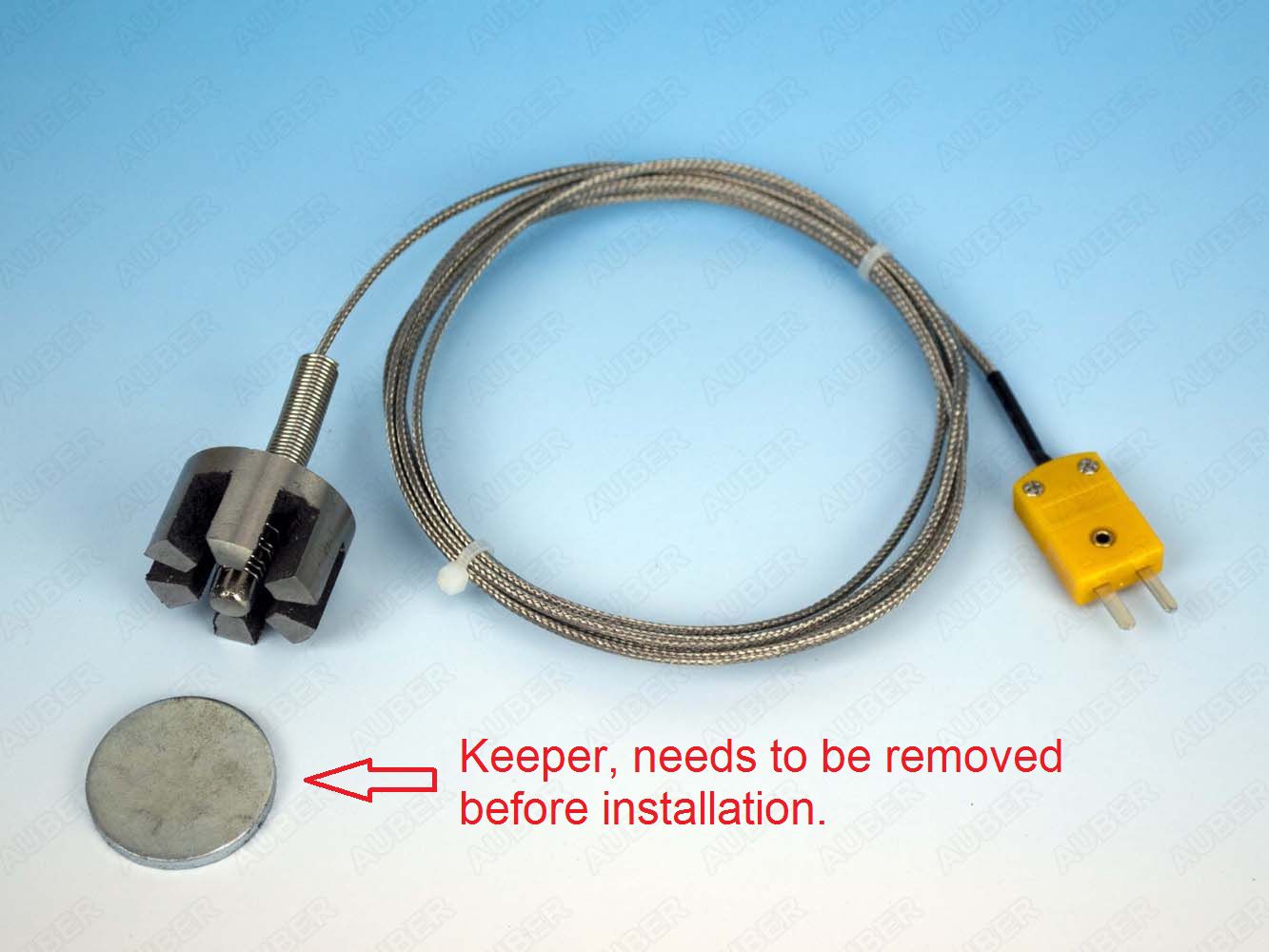
8. Why is my magnet sensor's reading much lower than a reference thermometer (TC-K-MAG)?
TC-K-MAG comes with a keeper during the shipping. To use this thermocouple, this keeper needs to be removed. Please see this picture for details.
TC-K-MAG sensor is mounted to the outside surface of the stove, so it is expected to read a lower temperature than the actual temperature inside the stove. It is easy and convenient to mount but only meant to give you a reference on how hot the stove is.